
Back at 25C3, pytey handed me a rather intimidating piece of hardware. “It’s a flash programmer, but it doesn’t work; I think I broke it with a custom adapter I was working on for it. I don’t have any tools to try to fix it, you want to have a go?”
Here’s the device:
The “Labtool-48UXP” is an “Intelligent Universal Programmer”, with an impressive list of features. Some of the ones that caught my eye were “Four DACs for Vcc, Vpp1, Vpp2 and Vpp3 with 8-bit resolution. Software controllable rises time and current limit protection”, “Logic driver supports pull-up/ pull-down or high impedance on all 48 pins with 2.0V-5V level,” and “The LabTool-48UXP performs device insertion and contact checks before it programs each device. It can detect poor pin contact and devices inserted upside down or in the wrong position.”
I had high hopes for this device — maybe I could write a Mac client for it, or add support for the Wii’s NAND flash chips to it. In any case, I could find virtually no info about this thing online; surely someone had hacked on one of these things before? In any case, before any more fun could be had, I had to get it working, and that required understanding what’s inside. Shall we take a look?
When you open the thing up, you’re faced with 2 stacked boards and a dual-voltage power supply (12v/5v).
The lower board is marked “LabTool-48UXP Control Unit”.
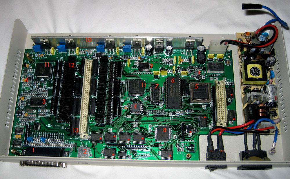
In some order, here are the major parts on the board:
- DB25 connector for parallel port
- USB connector
- Cypress “EZ-USB” FX2 microcontroller, a common USB2.0 interface that is an 8051-derivative
- Serial EEPROM to store USB VID/PID
- Main processor – an Intel 80C32, another ROMless 8051 derivative. This chip is as old as I am!
- Firmware for the 80C32 — 64KB, only the first half is used
- 32KB SRAM for the 80C32 — overlays the top 32KB of the address space. Also, I think some of the address space is used for memory-mapped IO with the XC3030 (see below) and the parallel port / FX2
- Lattice CPLD — possibly used for the MMIO mentioned above
- TLC7226C — 4-output 8-bit DAC. Presumably used to drive the 4 power supplies (Vcc, Vpp1, Vpp2, Vpp3) mentioned in the marketing copy
- Power supply section — what we have here is an LM317T (used as a general voltage regulator?), LT1170CT (used to boost the +12v to +30v), and then 4 power op-amps which are configured as non-inverting amplifiers with a gain of about 10. Meaning, the DAC feeds each a voltage from 0-3.0v, and the opamp outputs 0-30v.
- A6833 (x2) — these are 32-bit, high drive-capacity shift registers.
- NEC B772 PNP power transistors. There are 48 of them, but I don’t think that they necessarily map 1:1 with the output pins. These seem to be driven by the output of the shift registers?
- Reed relays — 10 of them. Why 10? Dunno. They seem to connect to the voltage sources, although 3 of them seem to pull stuff down to ground.
The chips marked with ? have the tops sanded off them. The chips marked with * are standard 74HCT logic-series chips — from top to bottom, left to right (like reading a book) we have ‘373, ‘245, ‘373, ’14A, ‘245, ‘244, ‘373, ‘374, ‘244, ‘244.
The upper board is marked “LabTool-48 Driver Unit”.
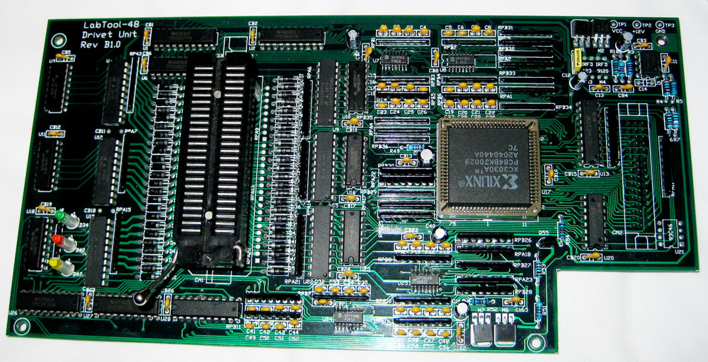
- TPIC6B259 “Power Logic 8-bit Addressable Latch”. This thing has 8 150ma open-drain outputs (wewt!) and only needs 4 control lines — 3 to specify 1 of 8 bits, 1 to actually set the bit. 6 of these, total, so one bit per pin.
- UDN2987 “8-Channel Source Driver with Overcurrent Protections”. This part has 8 buffers which are presumably used in combination with the open-drain latches (above) to form a push-pull circuit for each pin. Each driver can source 100mA, and it has an overcurrent detection output, which is fed back into the controller circuitry and causes the device to give you an error message when you put your chips in backwards. 🙂 Again, 6 of these.
- 74HC259 — 8-bit addressable latch. There’s one of these for every UDN2987, so you can latch the state of the pull-up driver and latch the state of the pull-down driver for each pin.
- 74HC138 and 74HC273, presumably acting as glue logic for the …
- XC3030A — Xilinx 3000-gate FPGA. Digikey lists this as a $17 part, but that must just be because they are old and hard to find! This was state-of-the-art, 10 years ago. If nothing else, it provides the “software controllable rise time”. I think it’s safe to say this drives the push-pull latches that cover the rest of this board.
Still unclear is exactly how the transistors and relays on the first board interact with the latches on the second board. My next post will talk about the software provided by the manufacturer to drive this thing.
8 responses so far ↓
1 skiddd // Feb 3, 2009 at 12:09 pm
The “hacked” version of this device is the “UP-48” which was a discontinued programmer from http://www.up48.com/english_site/product.htm
I have this as well as the updated versions but I find it very expensive to work with as you need to buy $$$ BGA/TSSOP adapters.
Nowadays, I just use the JTAG software from universalscan.com and design a simple PCB using eagle for the flash chip I want to dump. I put a blank coolrunner2 CPLD with the flash chip as well for the JTAG connections. It takes a very long time to dump big chips, but all in all it will just cost you about 10-15 U$D for the PCB even if the flash chip is a BGA type ;0) …
B.R.
2 liquitt // Feb 3, 2009 at 2:07 pm
this looks like pretty decent hardware, hope you can get it to work!
3 drewmerc // Feb 3, 2009 at 3:48 pm
http://www.aec.com.tw/
labtool home page
Features
* USB or parallel port interface with auto-switch power
* Support 5V and 3.3V low voltage devices, 1.8V chip support through low voltage adapter.
* Less then 2 seconds per Mbit Programming speed for high density flash chip.
* No adapter required for DIL chip up to 48-pin
* 48-pin universal pin driver and current limit
* Auto-sense/ Self programming with statistical report
* Device insertion /continuity check
* Universal adapter for 44-pin PLCC/ QFP/ TQFP/PSOP and 40/48 TSOP
* Supports OS : Windows 95/98/Me/2000, windows XP and NT (Parallel port)
Windows 98SE/Me/2000, windows XP (USB port)
* Automatic EPROM/ Flash ID search
* Serialization for Memory/μP chip
* Memory buffer H / L byte swap
* Project file save / load function
* User-selectable verify Vcc with one or two-pass verify voltage
* Automatic file format detection and conversion
* User-changeable programming parameters
* 1 years warranty
* Software update via web
Universal pin driver–No adapter required for DIL devices
* The LabTool-48UXP features universal pin driver, each pin can supply four different voltage, ground, it also can be configurable as TTL high/low levels with pull-high/pull-low, high-speed clock and high impedance. This advanced pin design lets you program any DIL device of up to 48 pins without needing an adapter.
Unbeatable programming speed
* The LabTool-48UXP’s on-board intelligence reduces system overhead to a minimum. The LabTool-48UXP has 100% more performance then its predecessor product in program the high density flash chip, it can program a Intel 32 M bit flash chip in less then 60 seconds.
Programming Speed Test Report
Intel 28F320C3B
AMD 29DL323DB
Blank check
18.6 sec
18.9 sec
Program
57.5 sec
76.2 sec
Verify
32.5 sec
33.0 sec
Total
108.6 sec
128.1 sec
* The LabTool-48UXP is much faster than its competitors, making it much more productive with today’s high density, multi-megabit memory devices.
Technological innovation and performance leadership
Device insertion and contact checks–No mistakes!
* The LabTool-48UXP performs device insertion and contact checks before it programs each device. It can detect poor pin contact and devices inserted upside down or in the wrong position. This function protects your pocketbook by preventing expensive chip damage due to operator error.
EPROM and Flash memory ID detection and Search
* Many EPROM and Flash memories have a build-in device ID and manufacturer ID. The LabTool-48UXP can read the device’s ID by press hot key to detect the ID and compare its database and determined the chip’s correct vendor and product number. This feature is especially useful with secondhand chips and devices that have had their part number accidentally (or intentionally) removed (this function only applied to 28 pin or 32 pin EPROM and Flash).
Auto-sensing and self-programming
* To meet mass-production requirements the LabTool-48UXP has implemented new patented technology in both its hardware and software. After entering the Mass-production Mode, the production line operator inserts a device into the ZIF socket. An LED on the LabTool-48UXP indicates the device is ready and the operator simply removes it and replaces it with a new one. No formal training is necessary adding flexibility and saving time and money. In addition, the LabTool-48UXP’s auto-sensing feature ensures the device has been inserted correctly and then automatically programs the device. Furthermore, in the mass-production mode the system keyboard is automatically disabled preventing the operator from making any inadvertent mistakes.
Project file save and load
* User can create and save a project file which contains device selection, buffer data and all the programming set-up options, this project file can be called upon at any time for future use without having to go through the setting up procedure again, your design file can easily pass to production department without making any mistake.
Serialization function
* If your memory devices need individual serial numbers with different increment sequence and initial value, the LabTool-48UXP has an Auto Increment function. This simply increments the serial numbers in the buffer each time a new device is inserted. This saves time and money.
User-selectable verify voltage, one or two-pass verification
* The LabTool-48UXP lets you select the verify voltage after you have programmed the device, e.g., Vcc, Vcc ±5%, Vcc ±10%. The Vcc voltage can be 2.0V to 6.5V. This feature ensures that your device has been programmed properly, preventing failures due to programming errors and ensuring data retention.
Non-DIL device support through versatile converters
* The LabTool-48UXP’s universal pin driver capability lets it program all 48-pin DIL devices, including all single-chip Micro-controllers, without DIL-to-DIL adapters. However there are many different packages beside DIL package, such as PLCC, SOP, TSOP, QFP and SDIP. We have developed over 100 different adapters to support these special-package devices.
Software update via web
* The LabTool-48UXP has additional safety features such as a built-in current limit and pin continuity check function. This prevents damage from faulty chips during the programming cycle. Software updates via web .
Universal 44-pin PLCC, QFP, PSOP and TQFP adapter supports 44-pin chip
* The universal pin driver on the LabTool-48UXP enables you to support all 44-pin chips such as EPLD, EPROM, Flash, EPLD and Micro-controllers. You need only one 44-pin universal adapter which eliminates the need to buy multiple adapters and saves money. Moreover, different package devices within 48 pins will only require one adapter.
Low voltage chip support
* The LabTool-48UXP support 2.0V ~ 5.0V logic level input/output, and it can supply 2.0V~21V analog voltage (such as VCC). Support lower then 2.7V low voltage chip such as 1.8V also possible by special low voltage adapter on top of its 48 pin ZIF socket.
Specifications
Socket and pin driver
* 48-pin DIL/ ZIF socket with receptacle for 8-pin to 48-pin 300/ 600-mil devices.
* Four DACs for Vcc, Vpp1, Vpp2 and Vpp3 with 8-bit resolution. Software controllable rises time and current limit protection.
* Logic driver supports pull-up/ pull-down or high impedance on all 48 pins with 2.0V-5V level.
Device support
* Memory : PROM, EPROM, EEPROM, Flash, Serial PROM, NVRAM
* Logic: PAL, GAL, CEPAL, PEEL, CDLD, EPLD
* Others: OTP/Flash Micro-controllers
Device operations
* Read, blank check, device insertion/ contact check, verify, checksum, EPROM ID check, compare, erase chip, function test, program, memory protect, device configuration setting, device search, edit buffer, mass production mode, modify vector, serialization, H/L byte buffer swap, buffer search.
PLD vector tester
* Accepts JEDEC test vectors up to 48 pins
* 2500V/usec. rise time
* File format conversion
* JEDEC, POF, Binary, Intel HEX, Intel EXT HEX, Motorola S, HP 64000ABS, Straight Hex and TEKTRONIC Hex, Automatic detection and conversion.
PC system requirements
* Operating system: Windows 95/98/Me,2000, Windows XP or Windows NT (Parallel port)
Windows 98SE/Me,2000,Windows XP (USB port)
* Processor: Pentium and above
* 128 MB RAM minimum, 512 MB recommended
* Hard disk with 100 MB free space
* Parallel port with EPP mode or USB port
* CD ROM driver
General
* Power: 100 to 240 VAC, auto-switching
* Frequent range : 47 to 63 Hz
* Power consumption : 25 W
* Operating temperature: 5 to 45 ℃ (41 to 113℉)
* CE & LVD certified
* Weight: 1.8KG
Download the most update LabTool-48UXP software for a trial.
LabTool-48UXP All device list.
4 drewmerc // Feb 3, 2009 at 3:49 pm
http://www.aec.com.tw/
5 ChipD // Feb 3, 2009 at 9:30 pm
Im gonna guess the ? chips:
ATmega of some sort
SPI flash of some sort
If i win do i get a prize? 🙂
6 natalic // Feb 4, 2009 at 12:08 am
Damn…That could be VERY useful when trying to test exploits and the such…Hopefully you can figure it out. Good luck bro! Keep up the amazing work!
7 eradicator // Feb 4, 2009 at 1:41 pm
It’s possible the FPGA is to blame for your inoperability.
I used to program Xilinx Field Programmable Gate Arrays in collage. It’s a basket of digital gates and acts as the primary controller (software, if you will) of the board you have there.
Xilinx has some software that makes it very easy to read and re-write the contents of these chips (and mod the design of what this board’s function is.)
This might get you on track as to the programming:
http://www.xess.com/prod023.php3
It’s a student version, but it has FPGA programming capabilities. The 3030 might need something more powerful as it was a commercially released chip.
This will help you with some understanding of FPGA programming, too:
http://www.cse.scitech.ac.uk/disco/publications/FPGA_overview.pdf
Verilog/VHDL is a common language for FPGAs and is similar to BASIC programming in many respects. We EE’s love that because most of us are not software engineers, but we all know BASIC from the DOS days 🙂
8 ukamak // Aug 22, 2014 at 5:10 am
It’s atmel tiny12
version: LabTool-48XP Security V1.0
You must log in to post a comment.